About Me

Salem Ali
Hey there! My name is Salem Ali and I'm currently a 4th-year at MIT, but I originally hail from
the Bay Area in California. I'm interested in mechanical design, product design, manufacturing methods, and testing.
Over the past few years, I've interned as a teacher at a robotics academy, at a solar installation company, as a hardware engineer at an automated retail start up, and
as a battery product design engineer at Apple. I also co-founded a company that is aiming to develop a low-cost ventilator.
Recently, I've been developing a hybrid power system for the MIT Earth Signals and Systems group, designing as part of my capstone class,
and learning how to play tennis!
Past Experiences
Below are a few of the broader categories I have experience in
Analysis
The first part of MIT's Mind and Hand mantra, is the analysis. I have been able to leverage what I learned in my classes as crucial elements of my projects.
Design
I have completed multiple projects where I was able to practice my design skills, whether it be simple CADing personal projects or as part of a longer, iterative process.
Manufacturing
On the other side of the MIT's Mind and Hand is manufacturing, and I have practiced my manufacturing skills greatly. From mills and lathes, to CNC Hasses, to injection molding, thermoforming, and so much more, I have garnered experience actually making the products I designed.
Portfolio
Here are projects I've worked on!

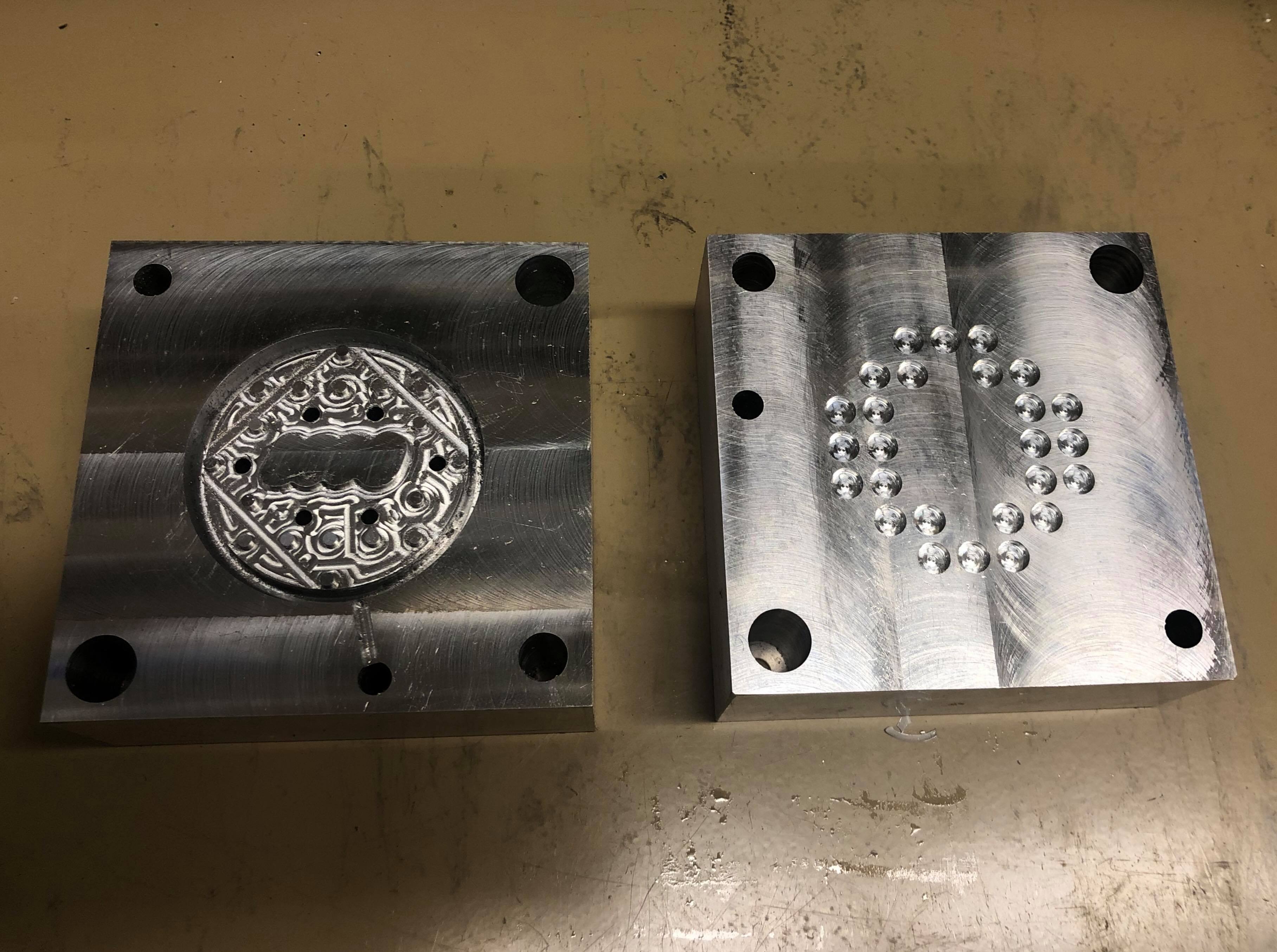
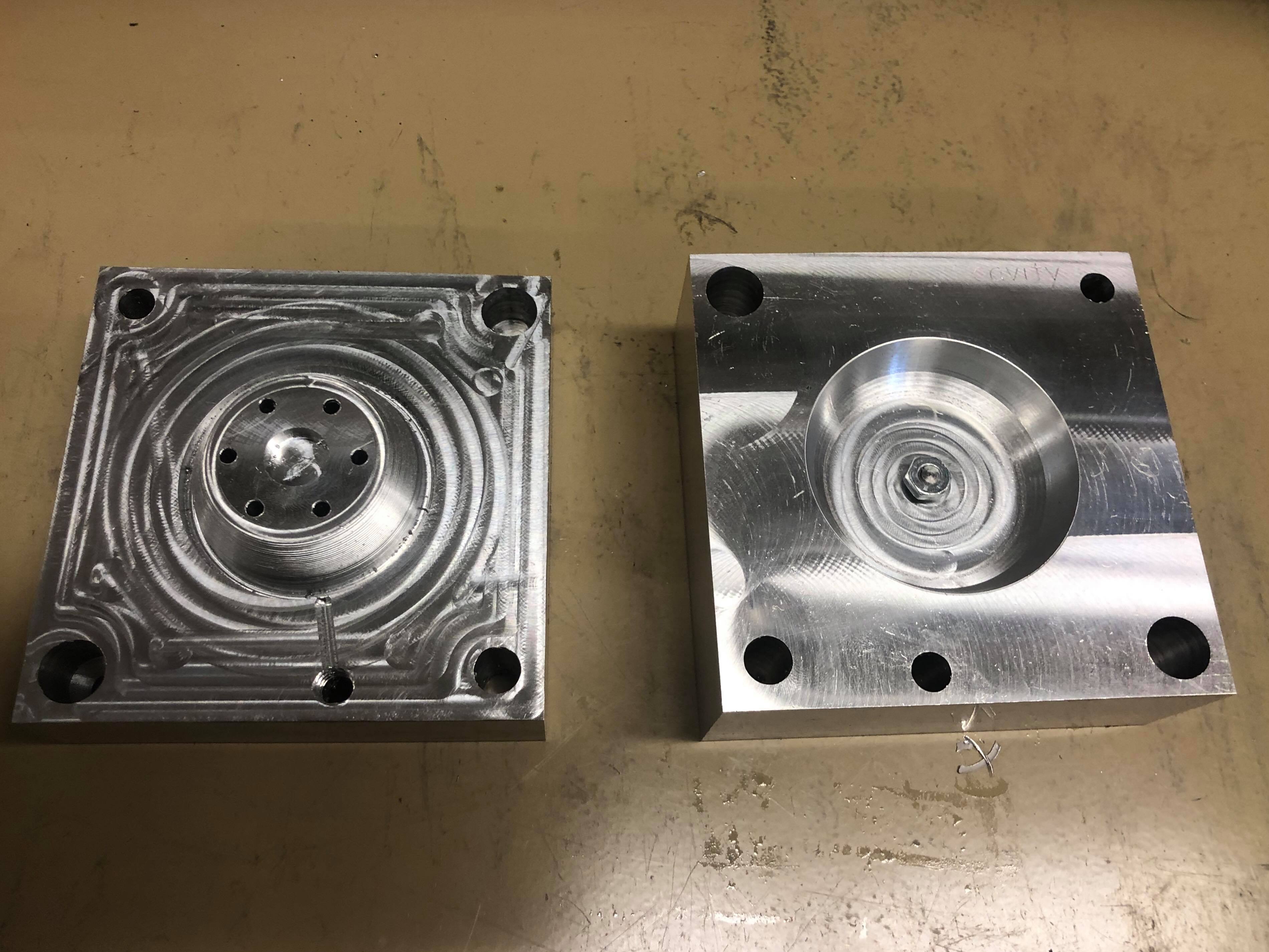
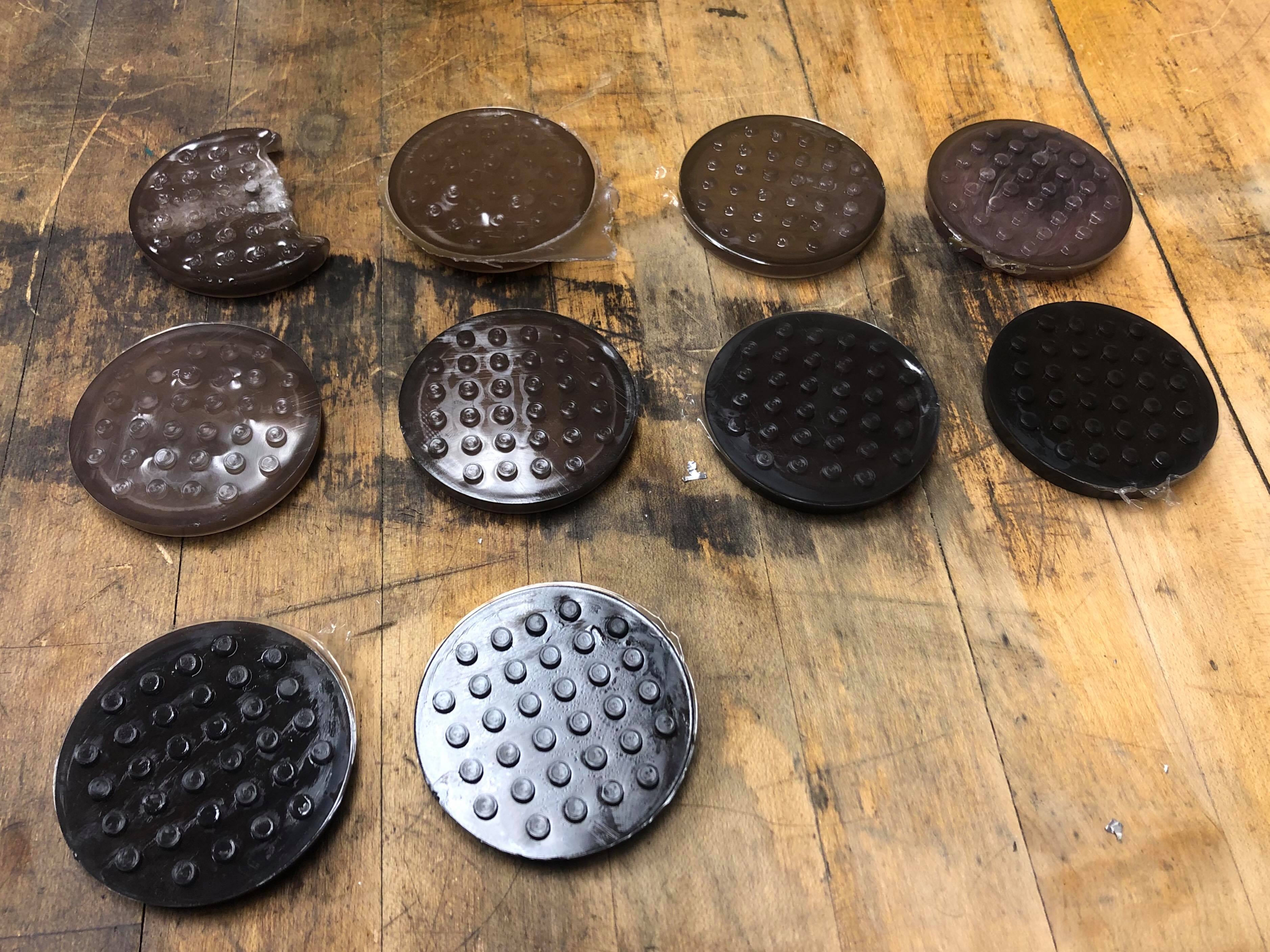
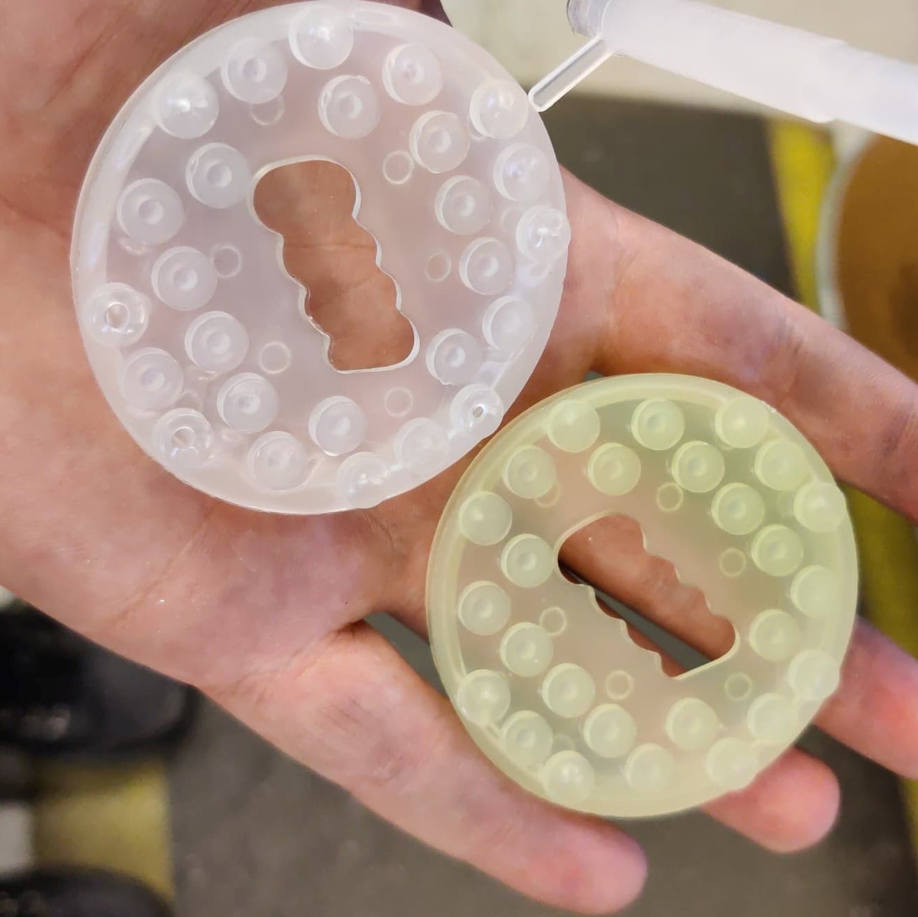
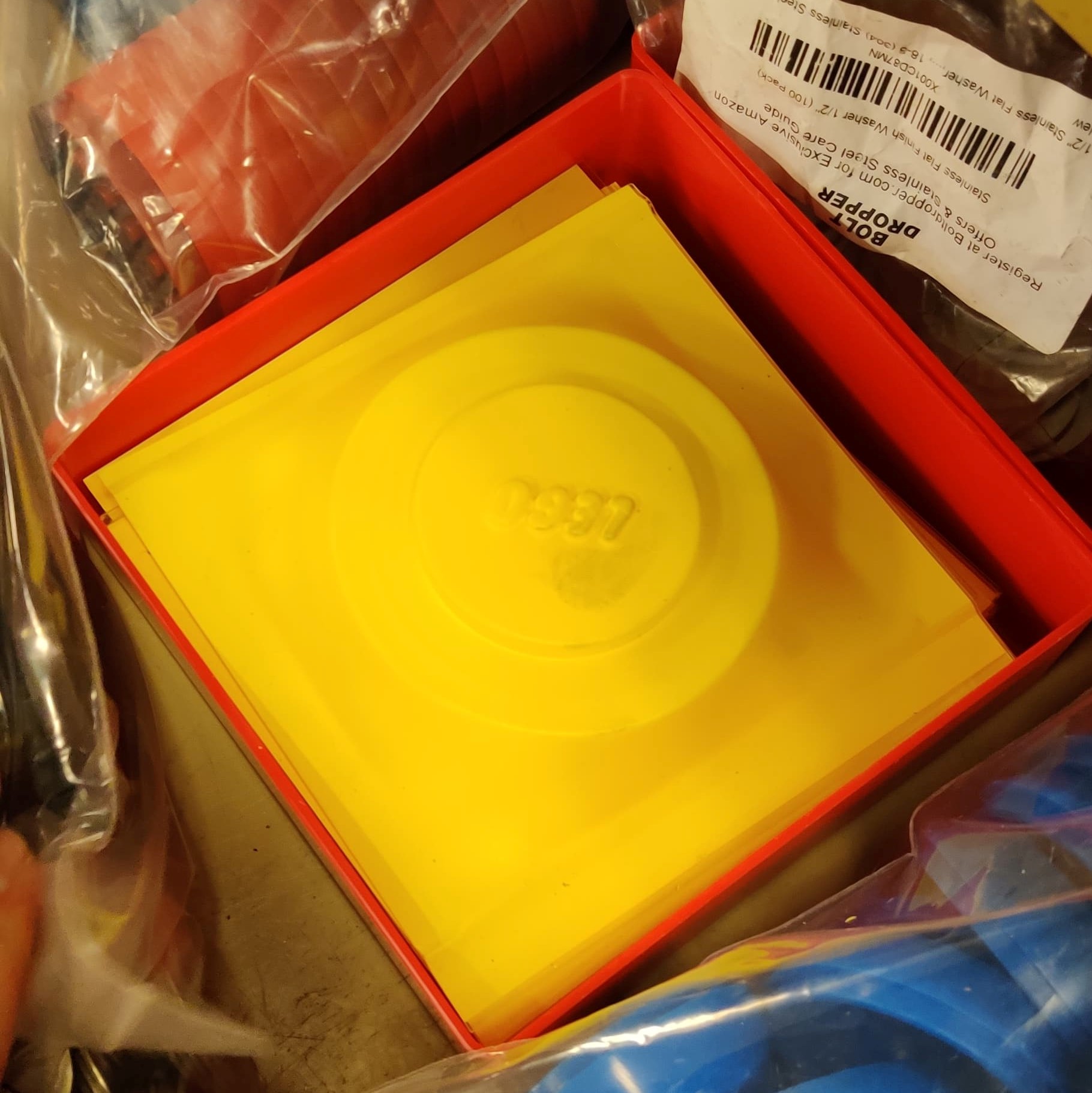
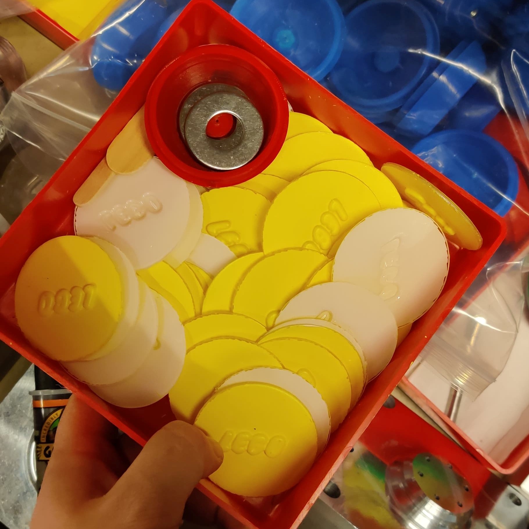
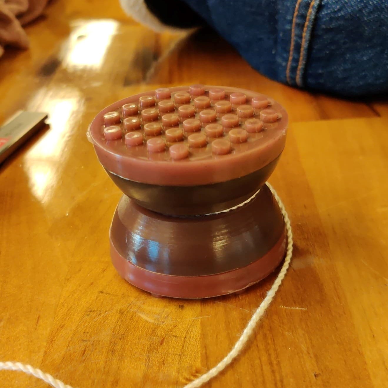
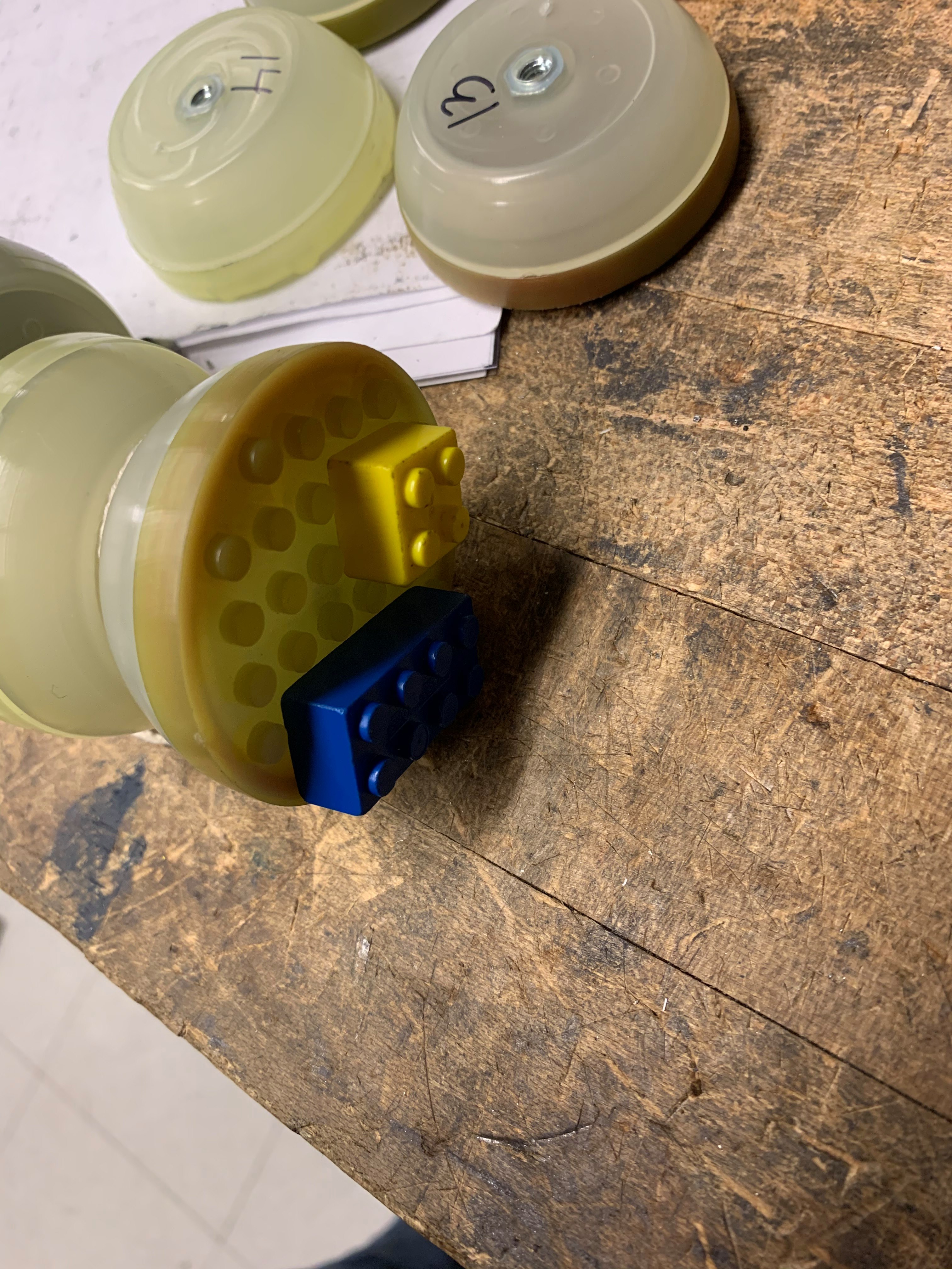
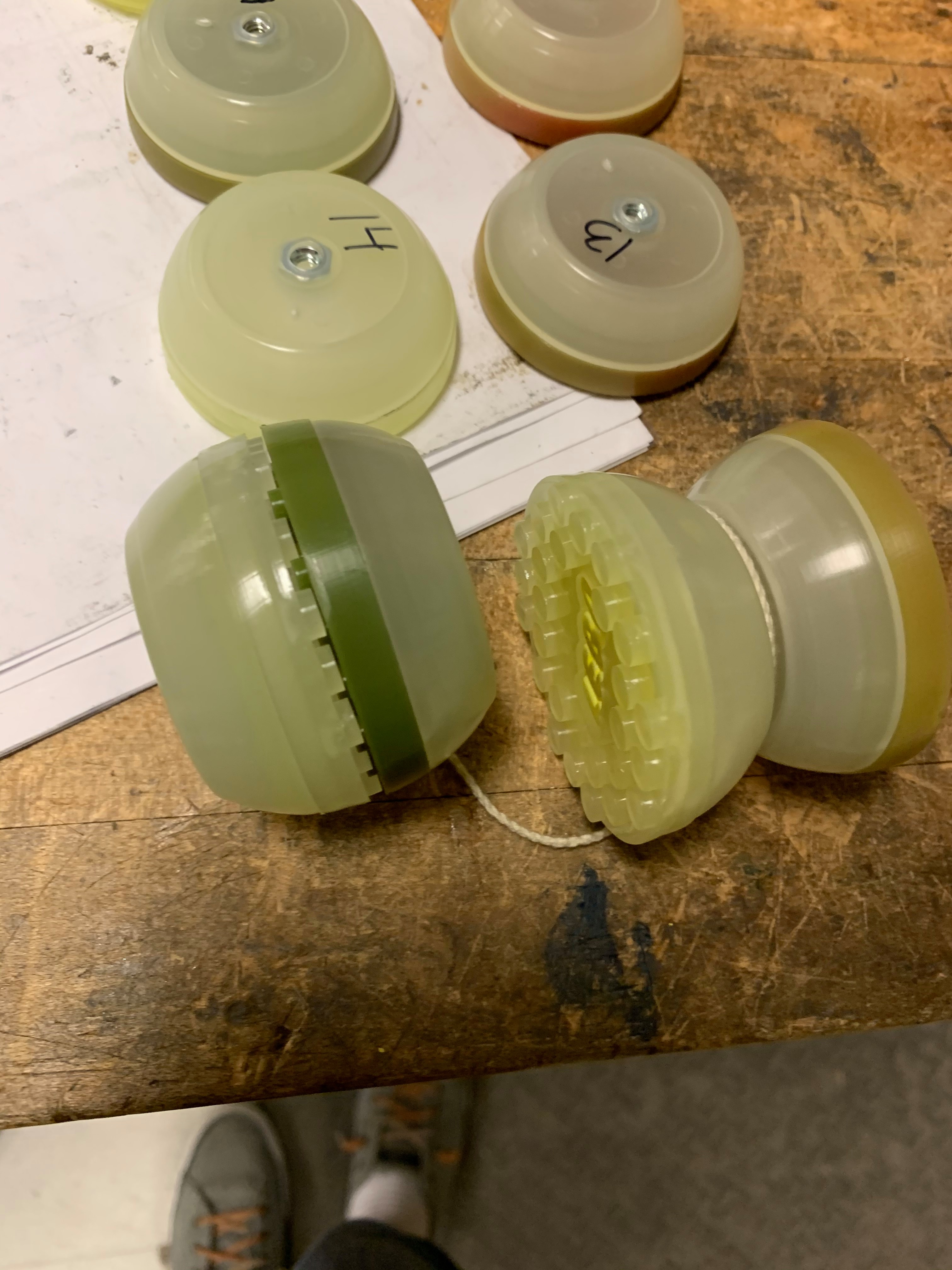
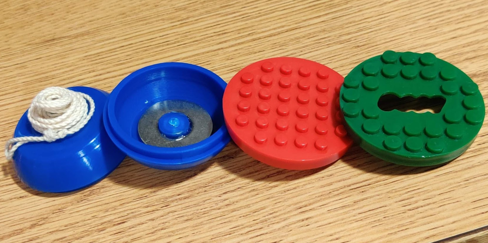
Yoyo
Design, Manufacturing
.jpg)
Thermal Case Study 1: Cylinder
Analysis
.jpg)
Thermal Case Study 2: Skillet
Analysis
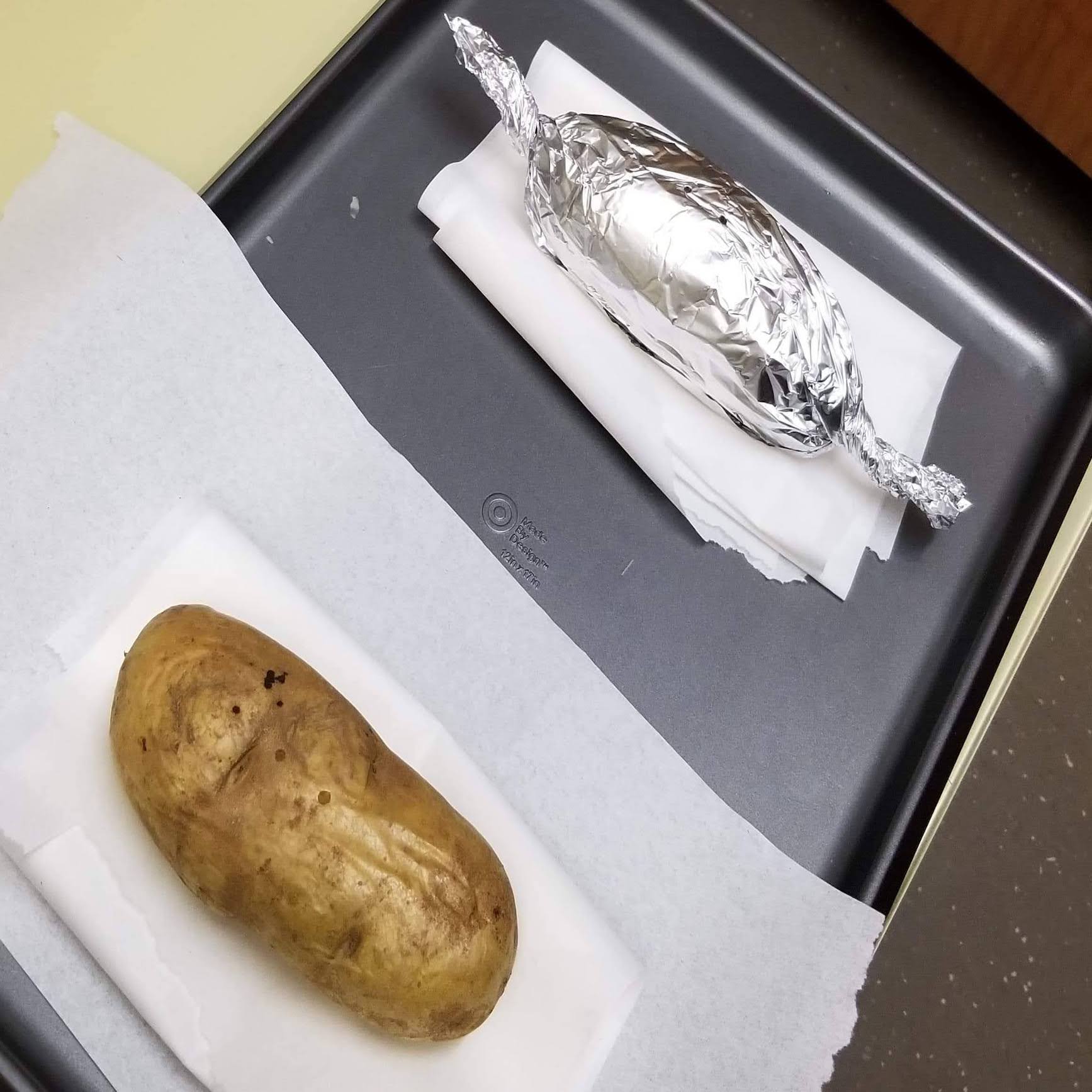
Thermal Case Study 3: Potato
Analysis
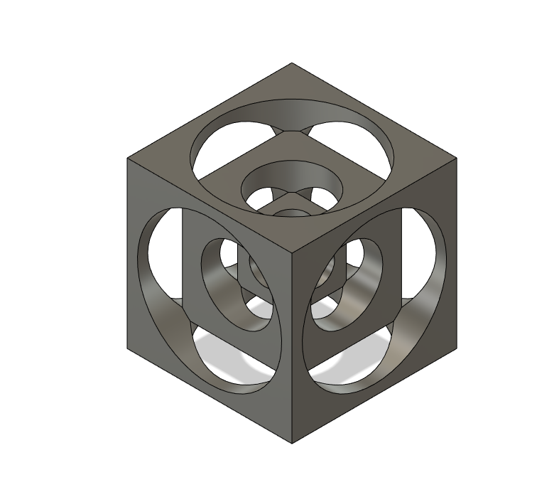
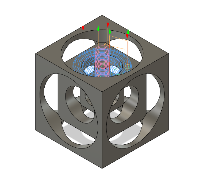
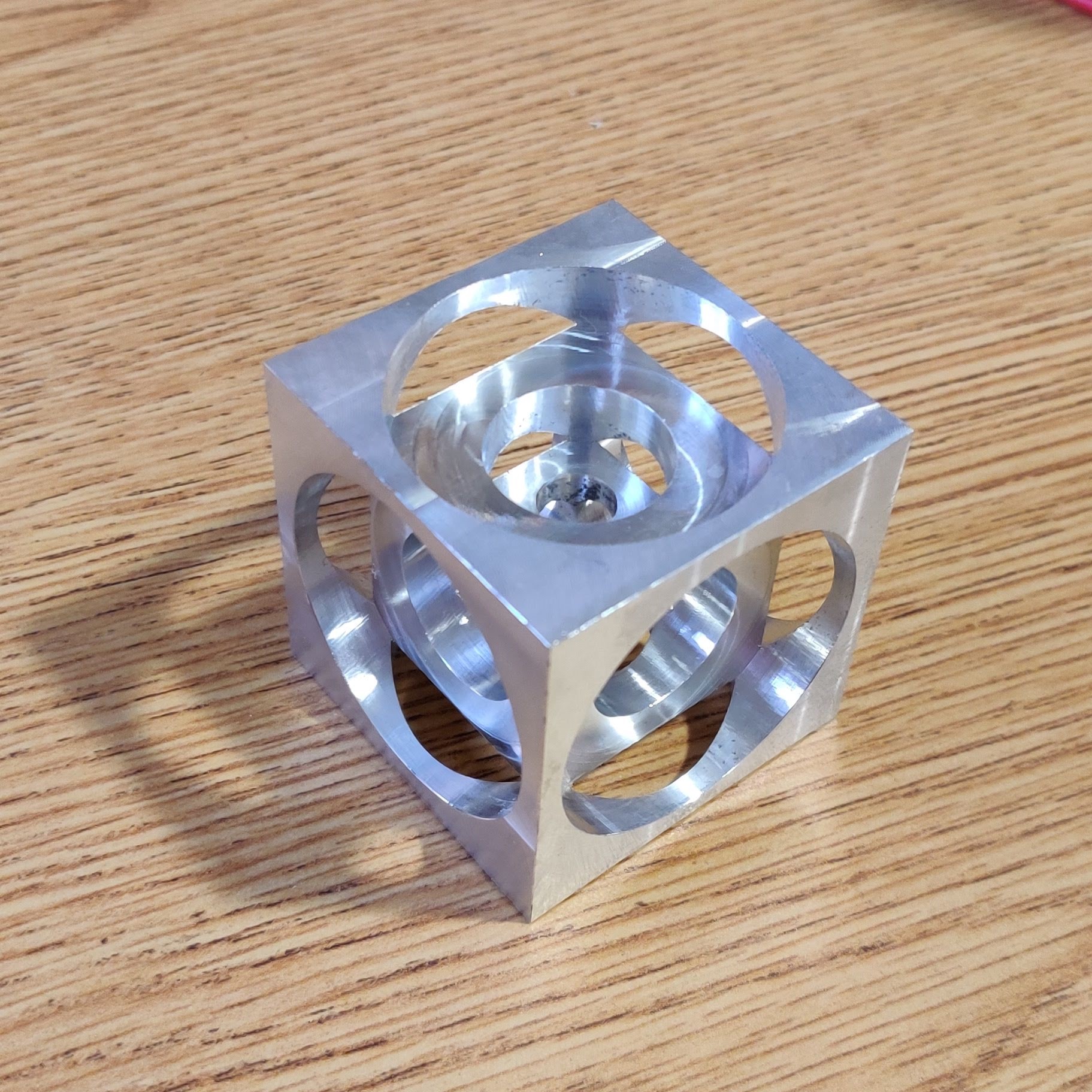
Turner Cube
Design, Manufacturing
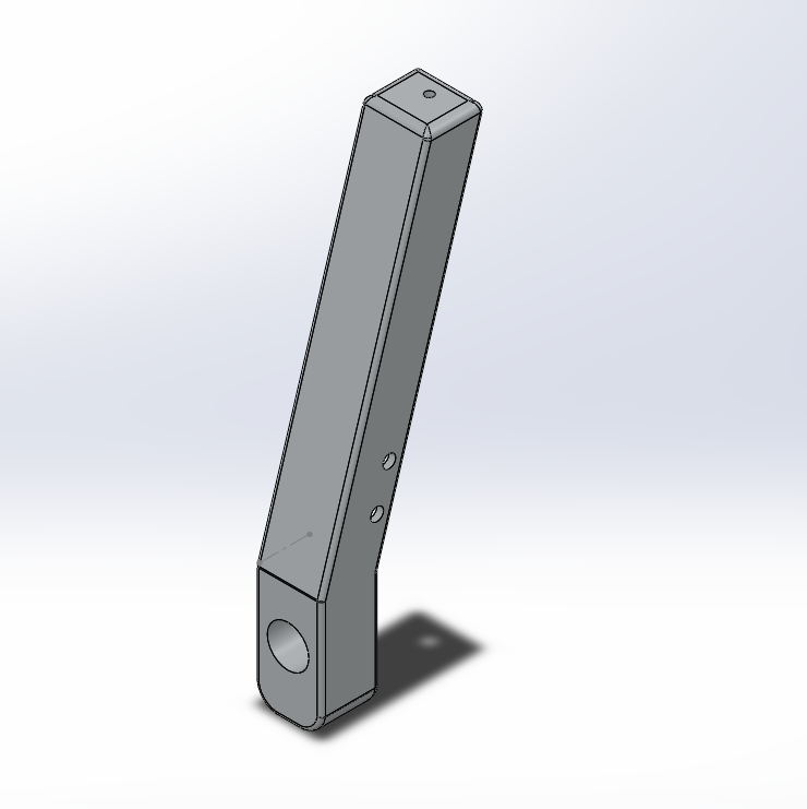
Upright
Manufacturing
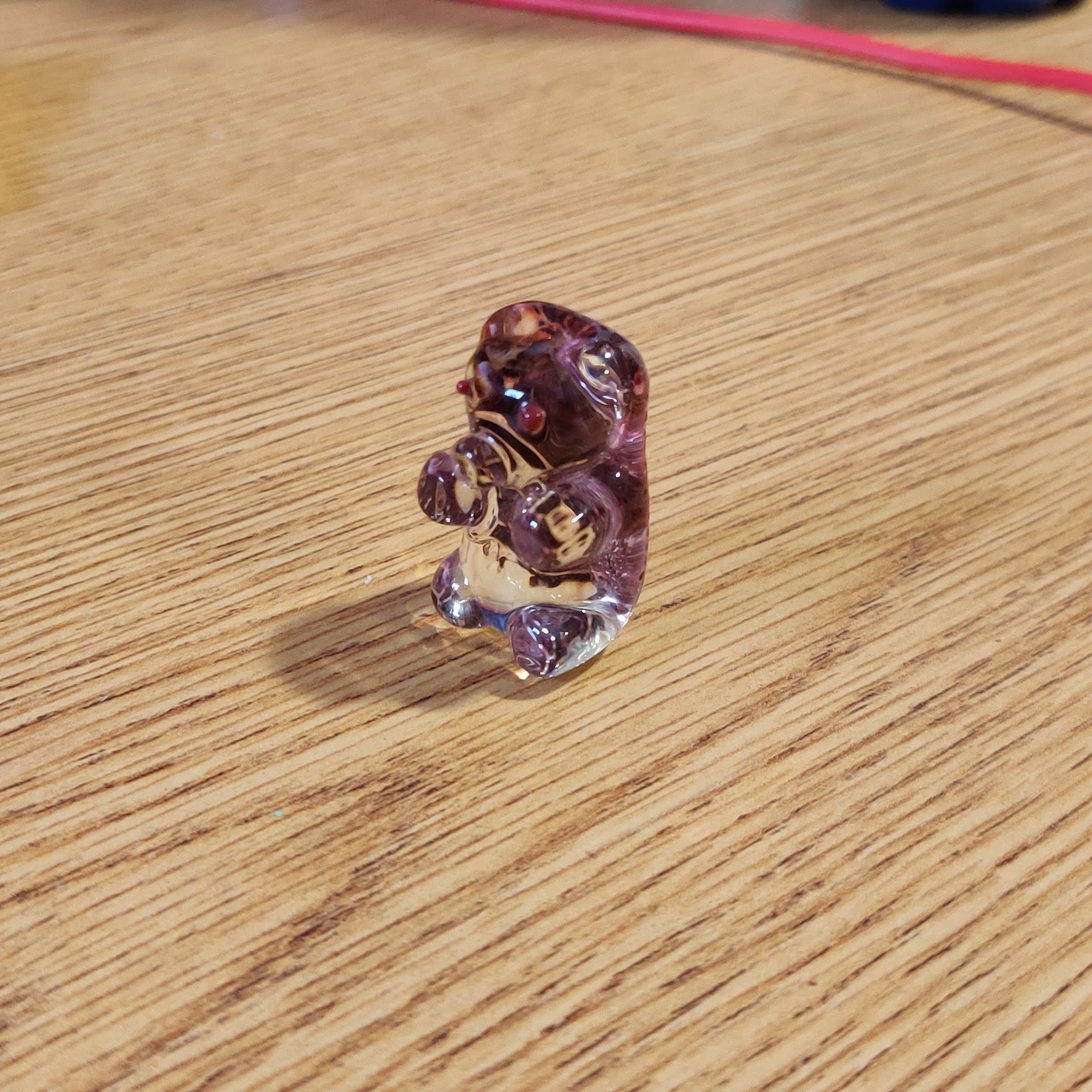
Glass Bear
Manufacturing

Truck
Design, Manufacturing

Suspension Lower A-Arm
Analysis, Design, Manufacturing

Competition Robot
Analysis, Design, Manufacturing
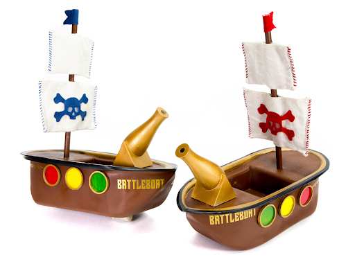
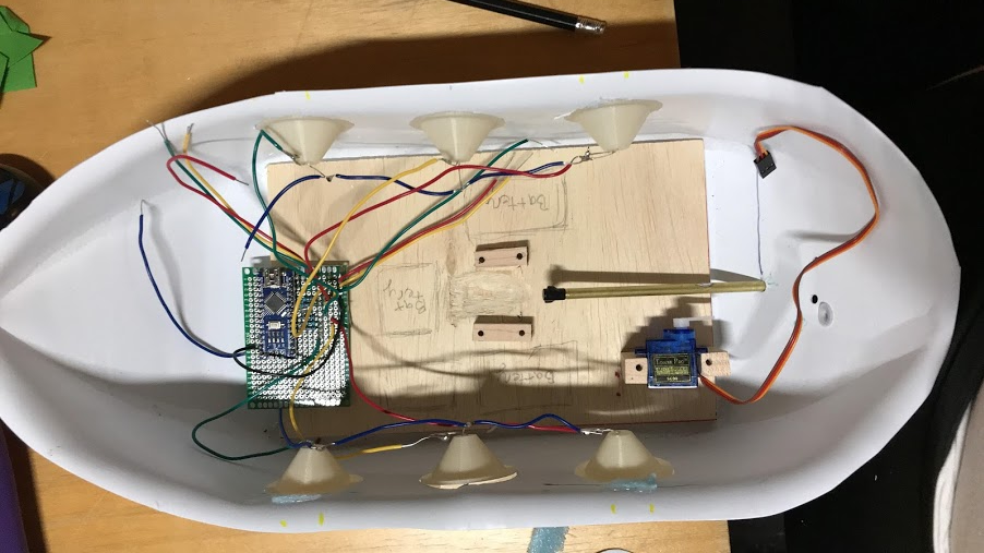
BattleBoats
Design, Manufacturing